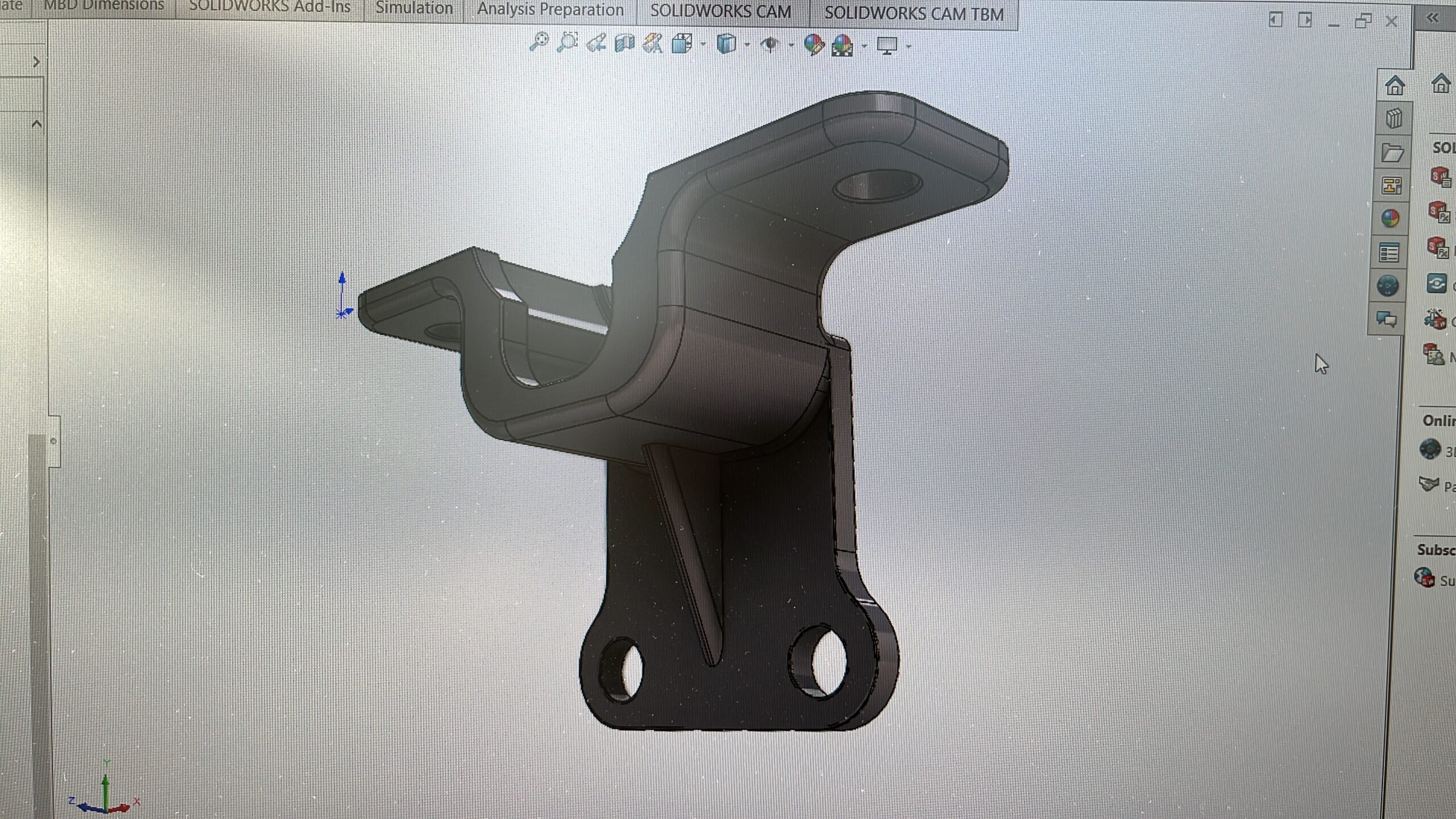
Steering Column Lifter Bracket
Below is a photographic narrative to describe the bracket including ‘before and after’ photos showing the height difference and the new bracket installed at various stages.
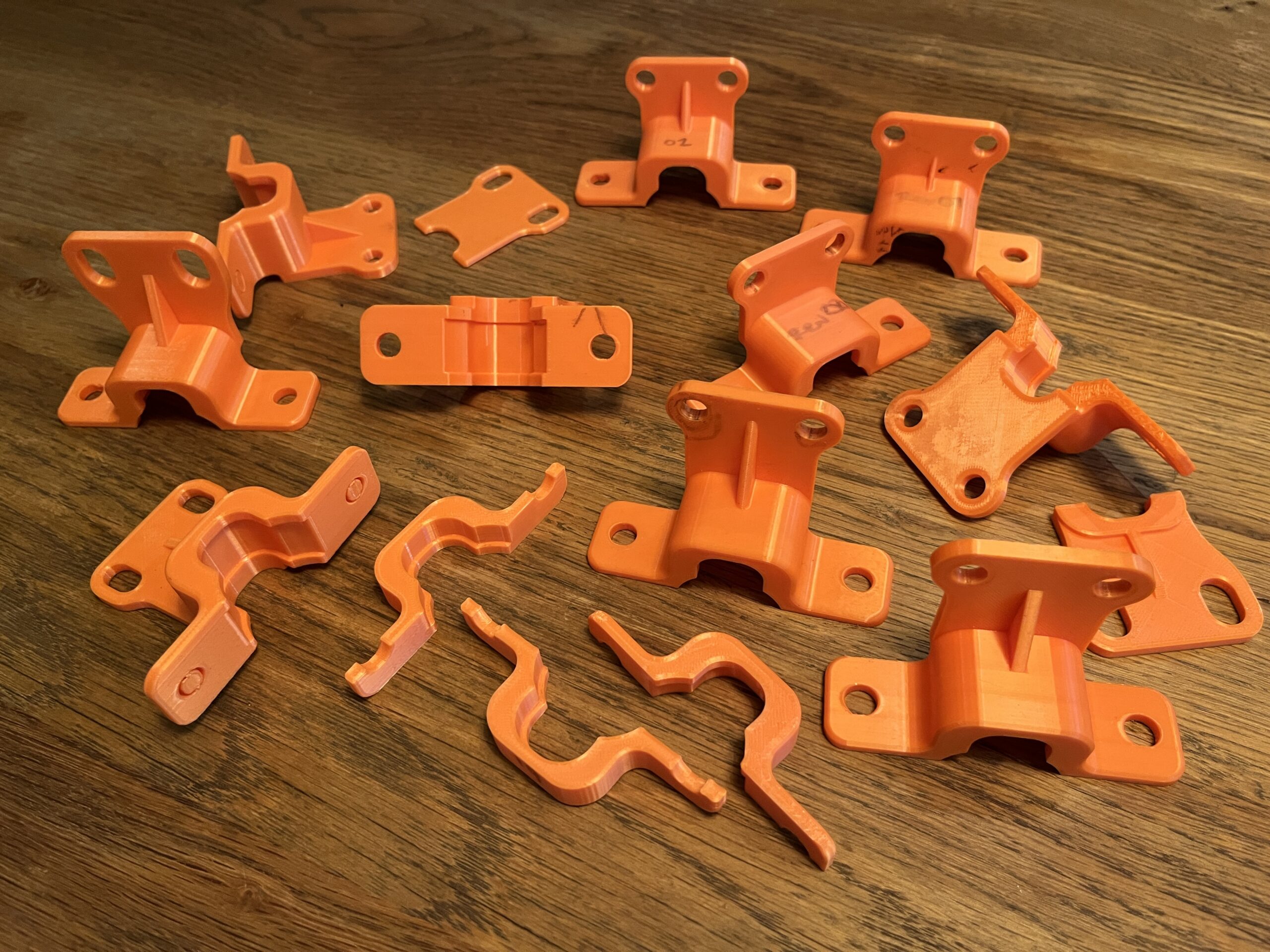
A gallery is also included of the bracket development for those who are interested. Any comments or queries on the bracket, do please get in touch, we’re happy to share any details!
My own car is a ’74 TR6 (US model LHD) which runs and drives beautifully (at least it did before the dash was removed…) and is somewhat of a test mule for current projects, far from a perfectly restored example therefore! But with currently good access for the photos, if you’d like to see photos of anything we missed for the bracket, do please ask and we can add it here!
(mobile users, this page best viewed in landscape)
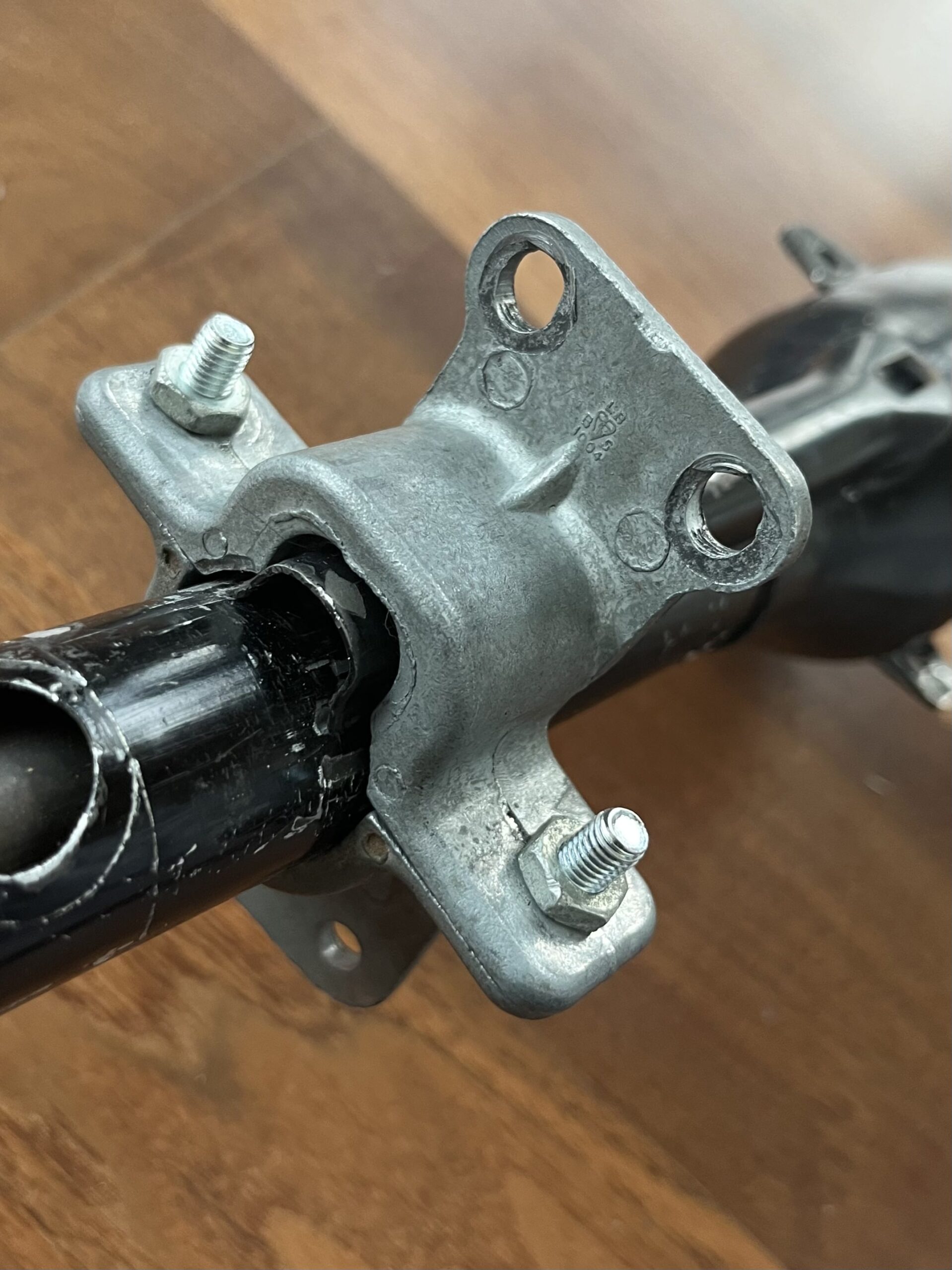
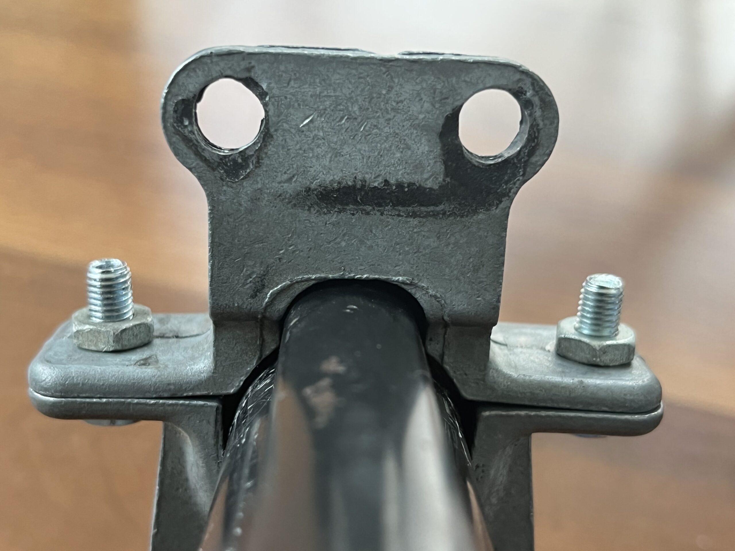
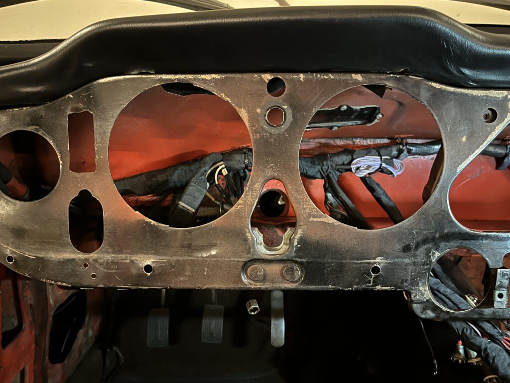
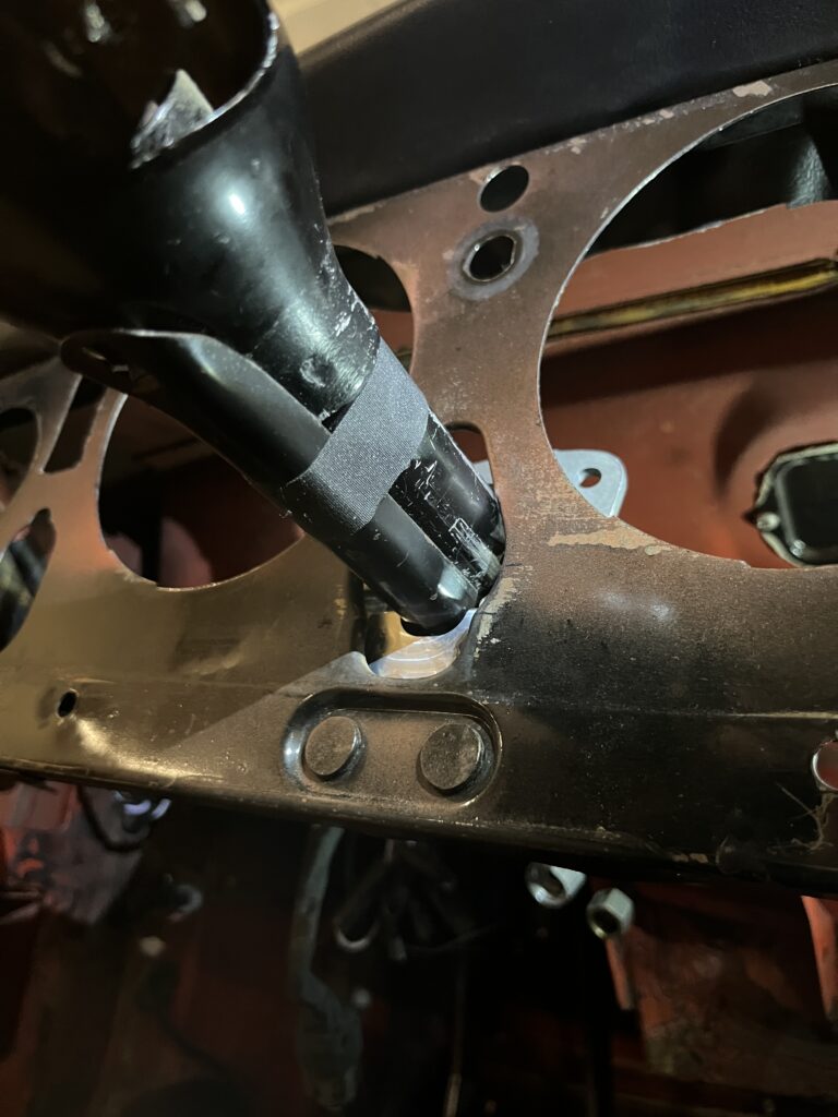
The original bracket as installed in the car.
The bracket is bolted to two captive bolts on the back of the dash metal fascia (photo is taken from the backside of the dash looking back to the drivers seat).
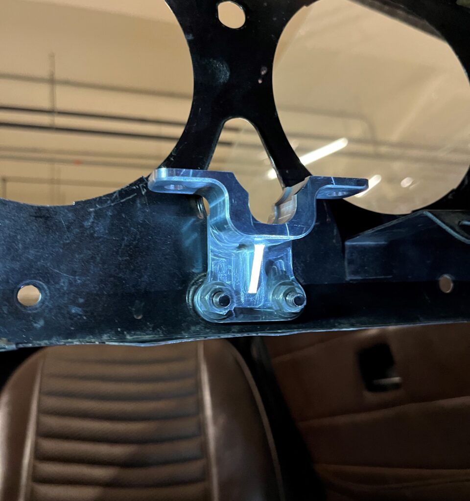
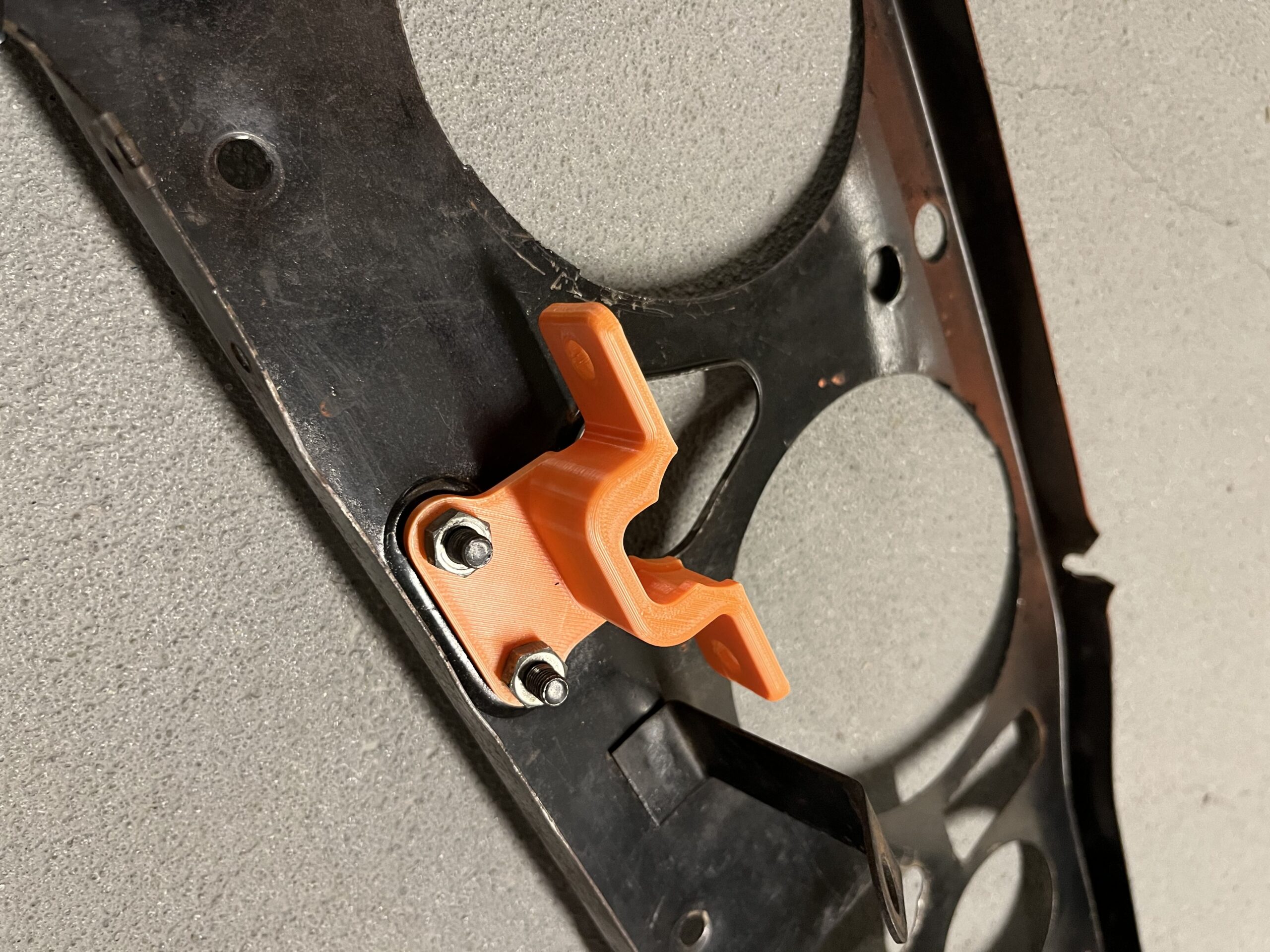
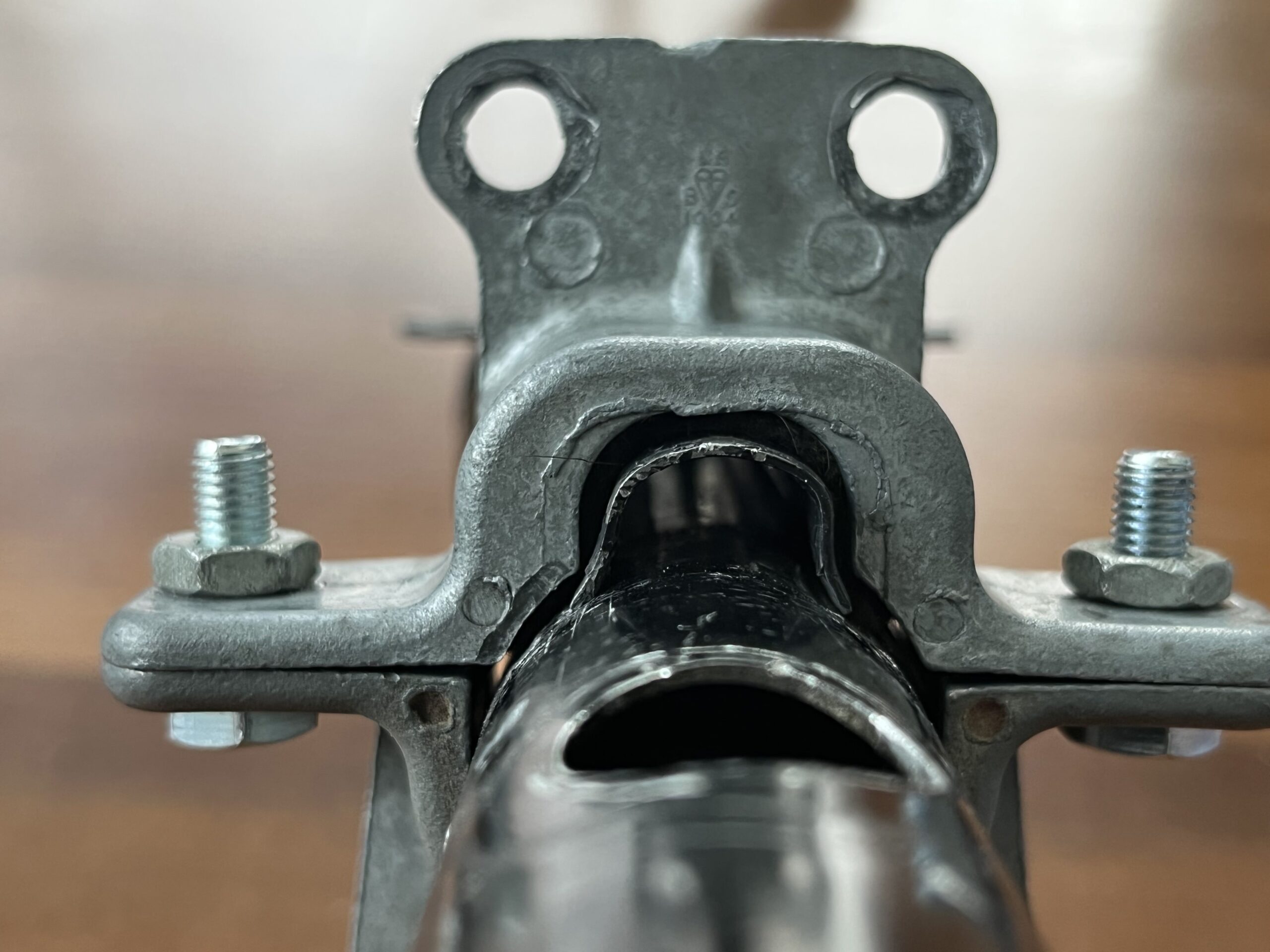
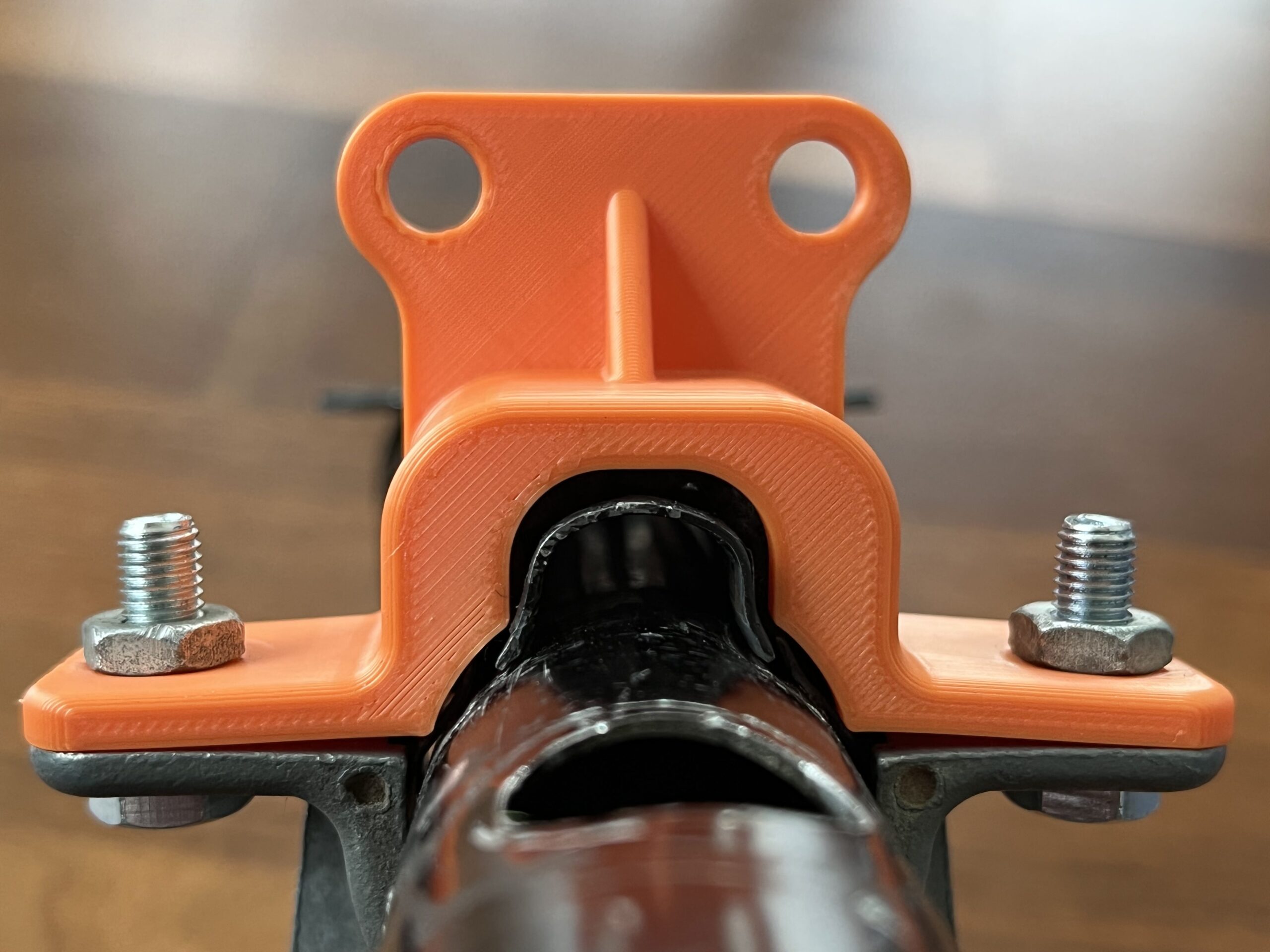
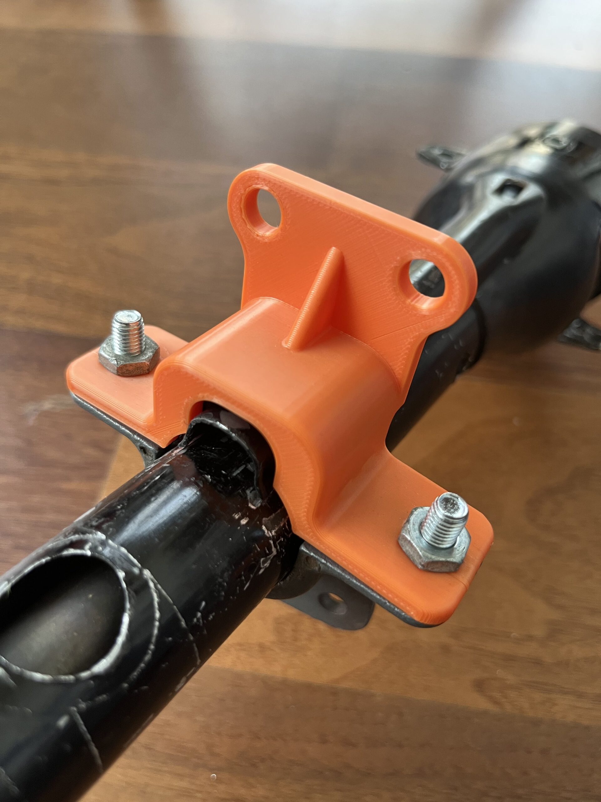
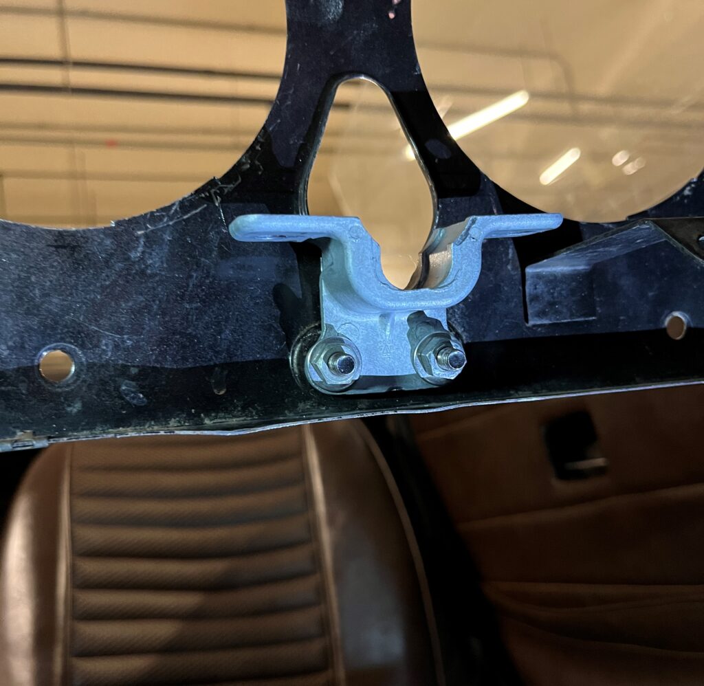
The new replacement clamp installed in the car. It replicates the original clamp in all dimensional aspects, and bolts to the dash in the same manner. It differs only in its ‘height’, moving the position of the steering column vertically upwards.
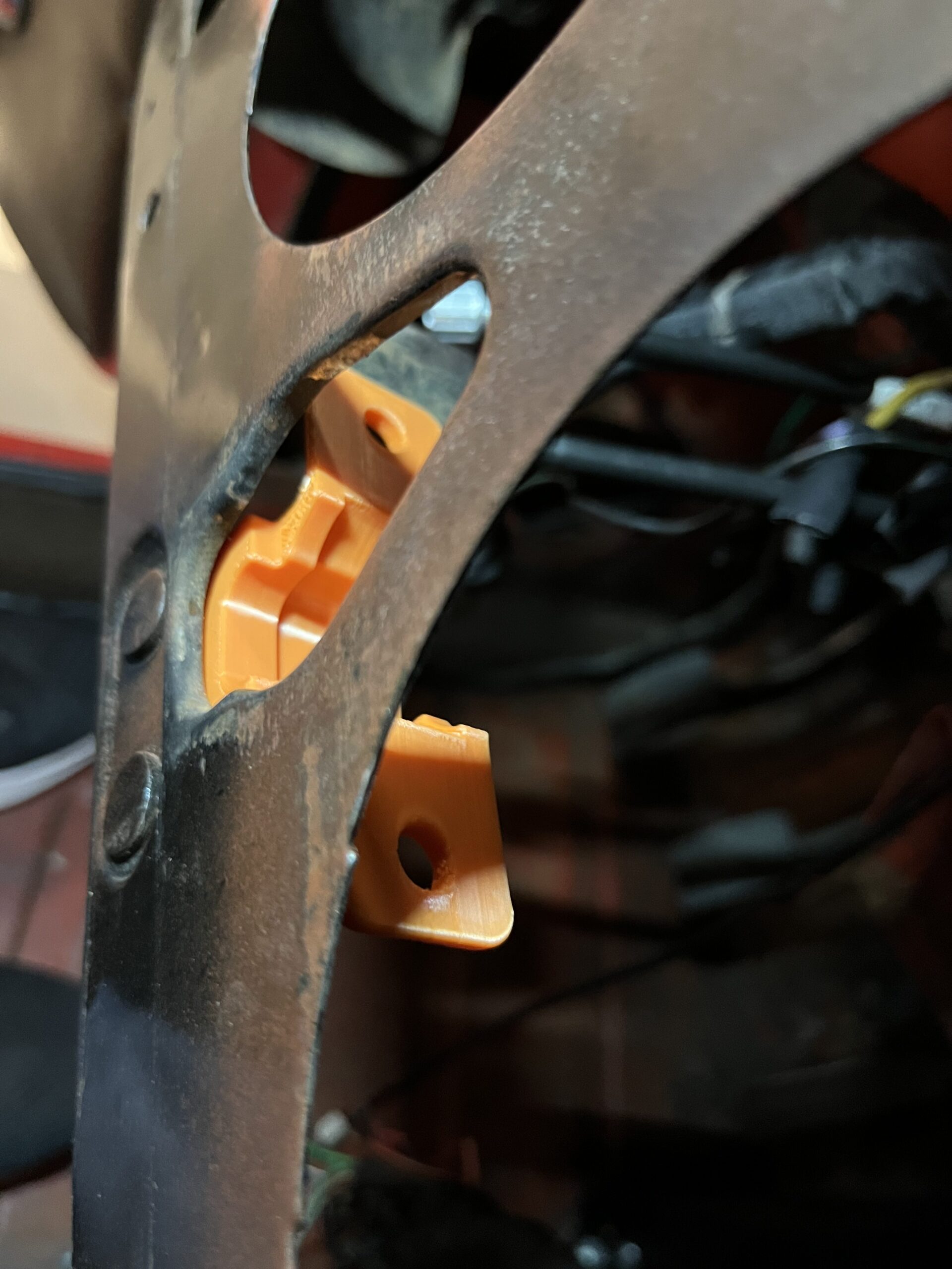
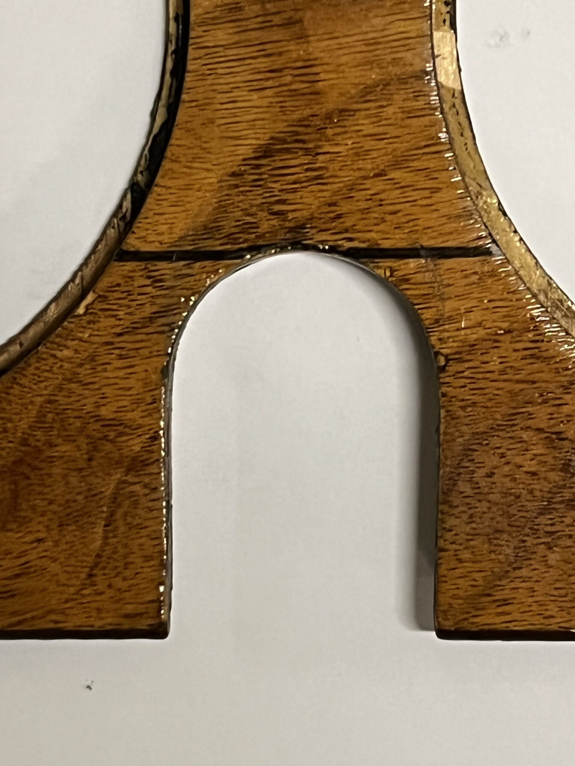
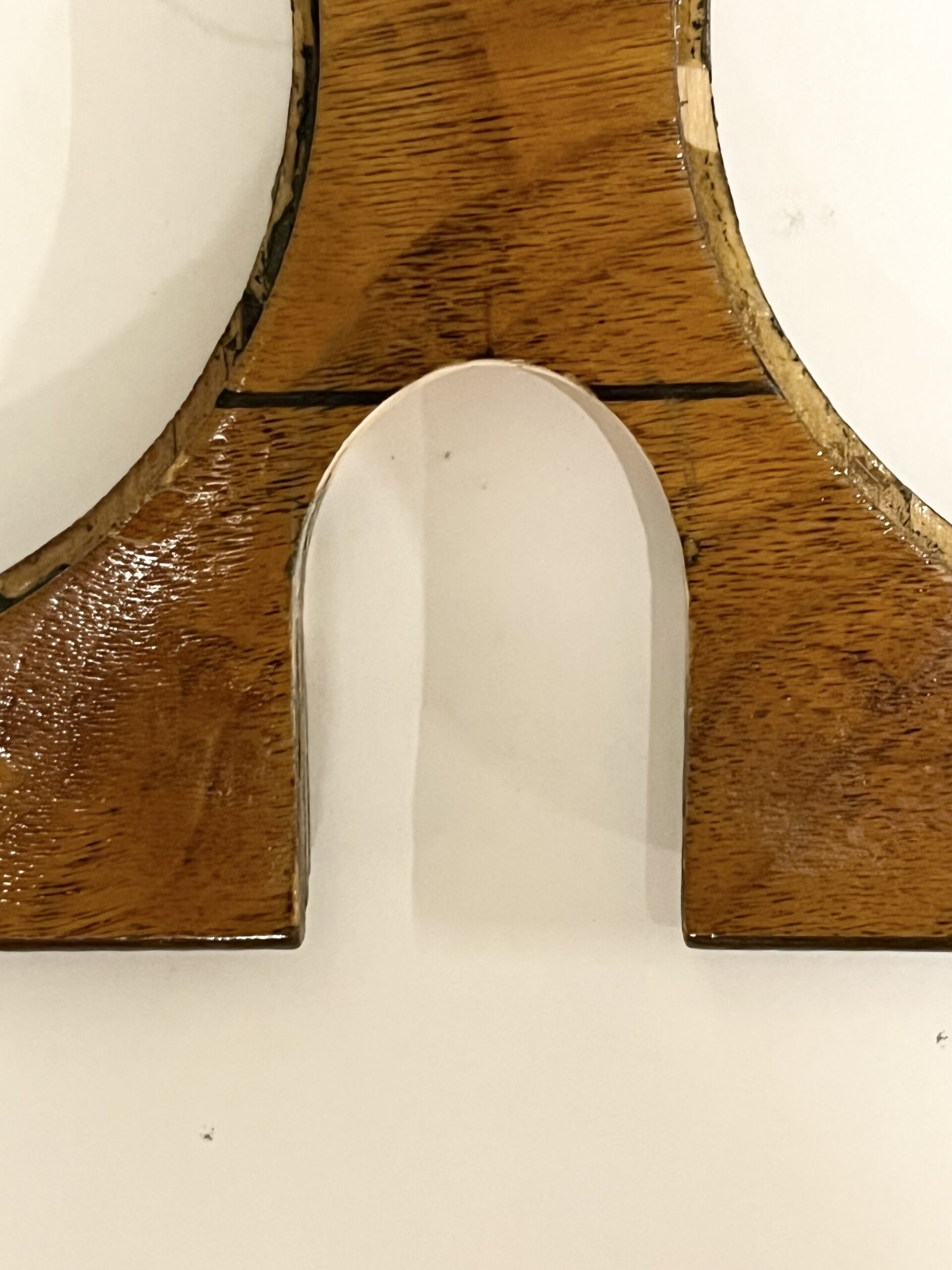
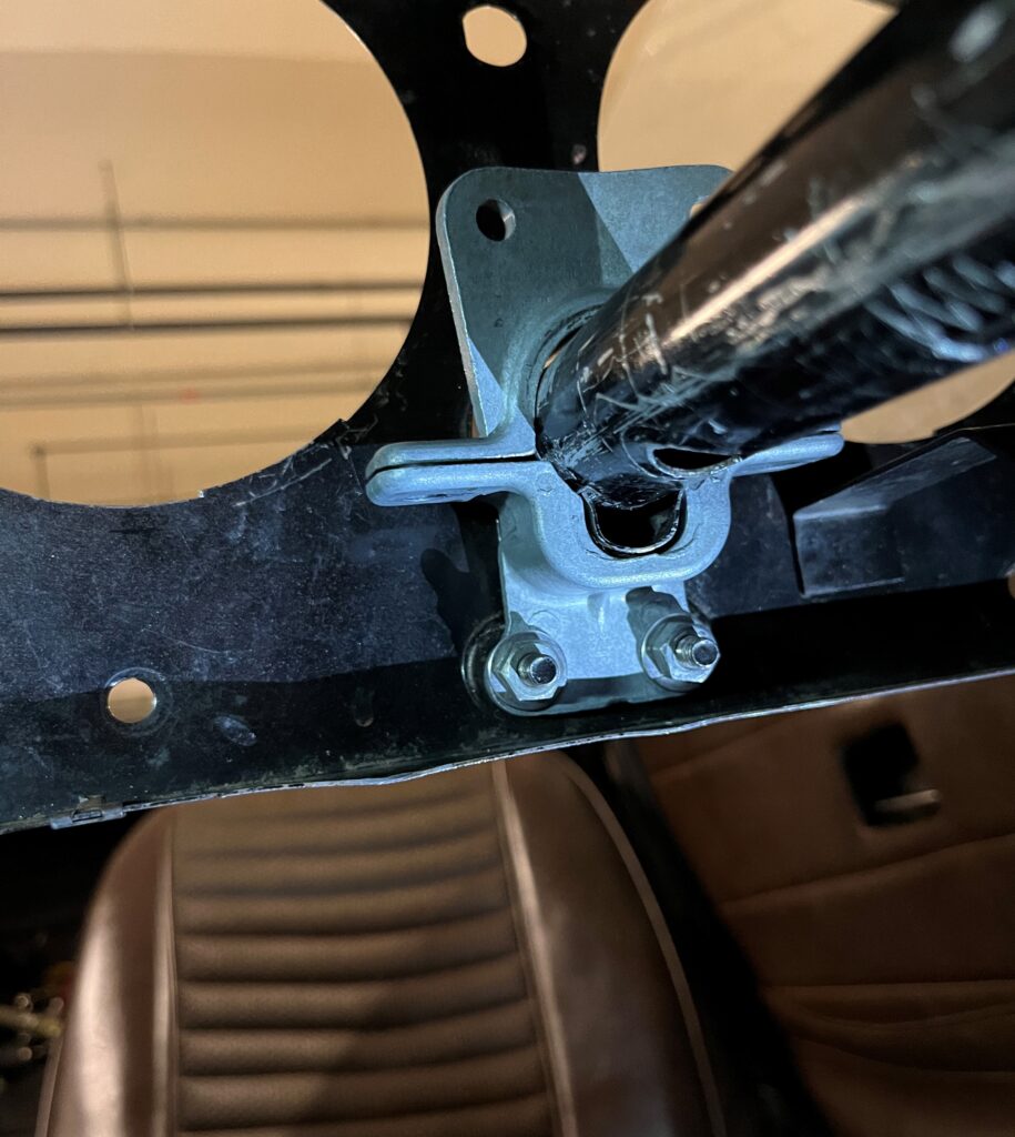
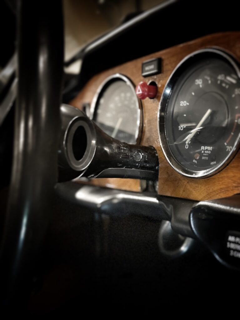
The original bracket as installed in the car, viewed from the drivers seat. The teardrop shaped opening around the bracket is the ‘available space’ where the steering column can be lifted to raise the steering wheel height.
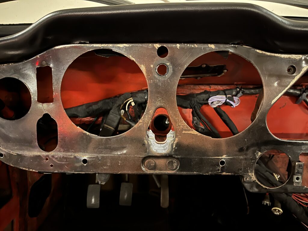
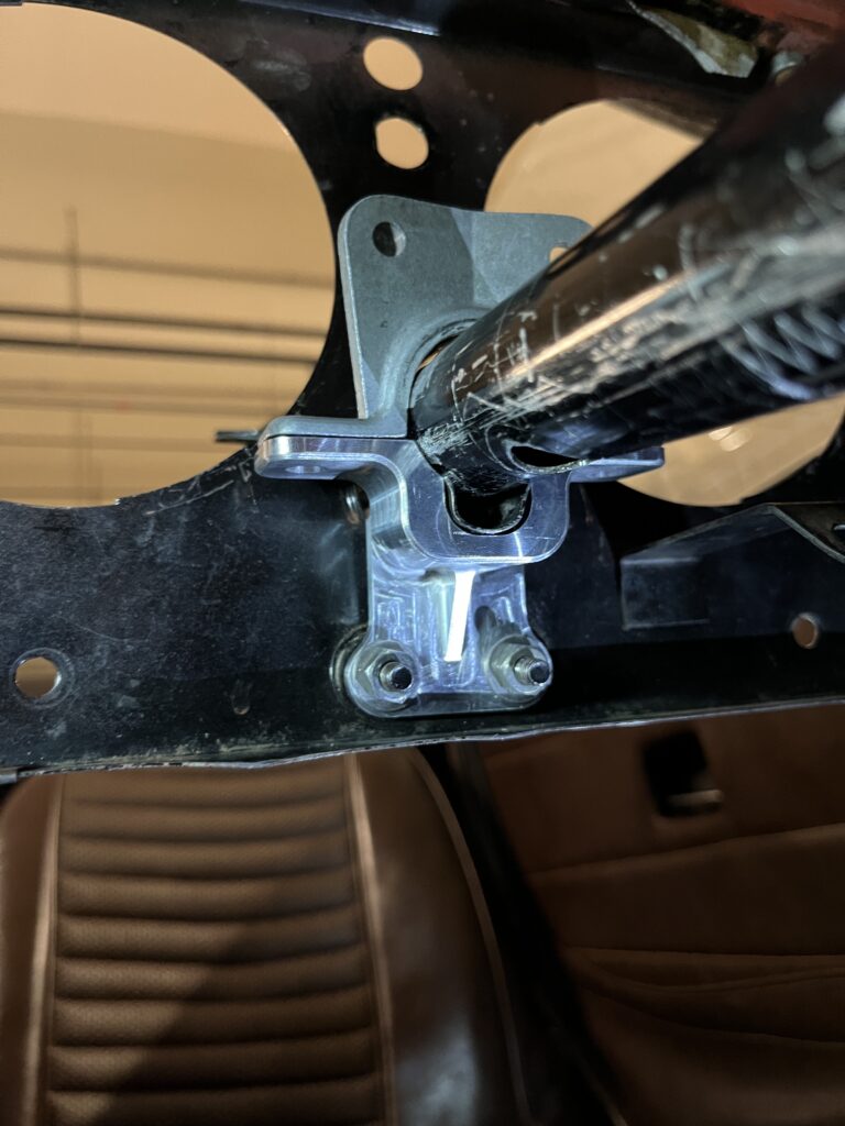
The new bracket as it appears installed in the car.
The original bracket, shown with the ‘top clamp’ and steering column (including the ‘spring clip’ and felt liner inside the clamp).
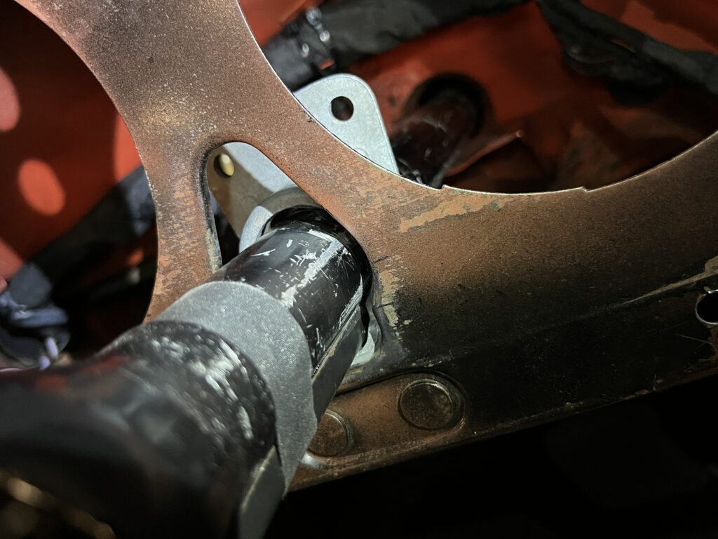
The new bracket as it appears installed in the car together with the ‘top clamp’ and steering column (including the same ‘spring clip’ and felt liner inside the clamp).
The original top and bottom clamps as installed in the car together (viewed from behind the dash) with the steering column in place. (clamp bolts not shown for clarity, see later photos).
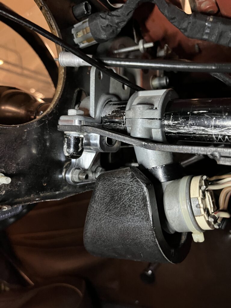
The new bracket as installed in the car (viewed from behind the dash) together with the top clamp and steering column.
The new clamp installed in the car, shown with the original bolts (torqued down in this photo), with the original ‘anti-torque plate’ and original ignition. (note the ignition clamp is not torqued down as we no longer run the ignition in this location, but included here to confirm fitment for those that do).
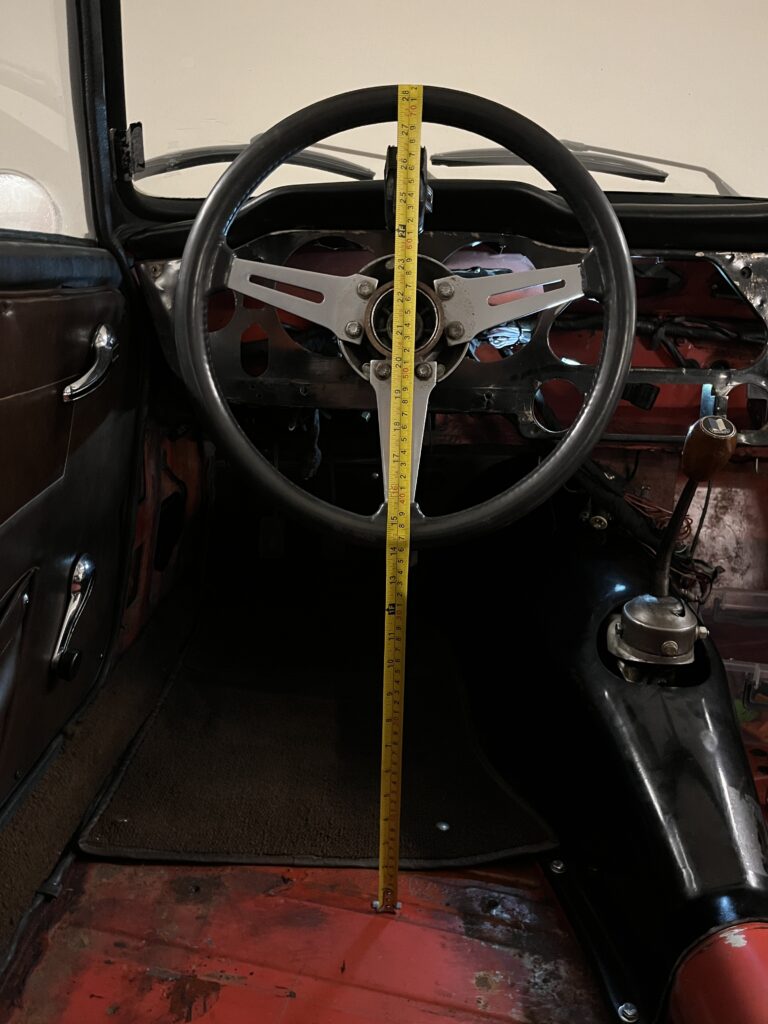
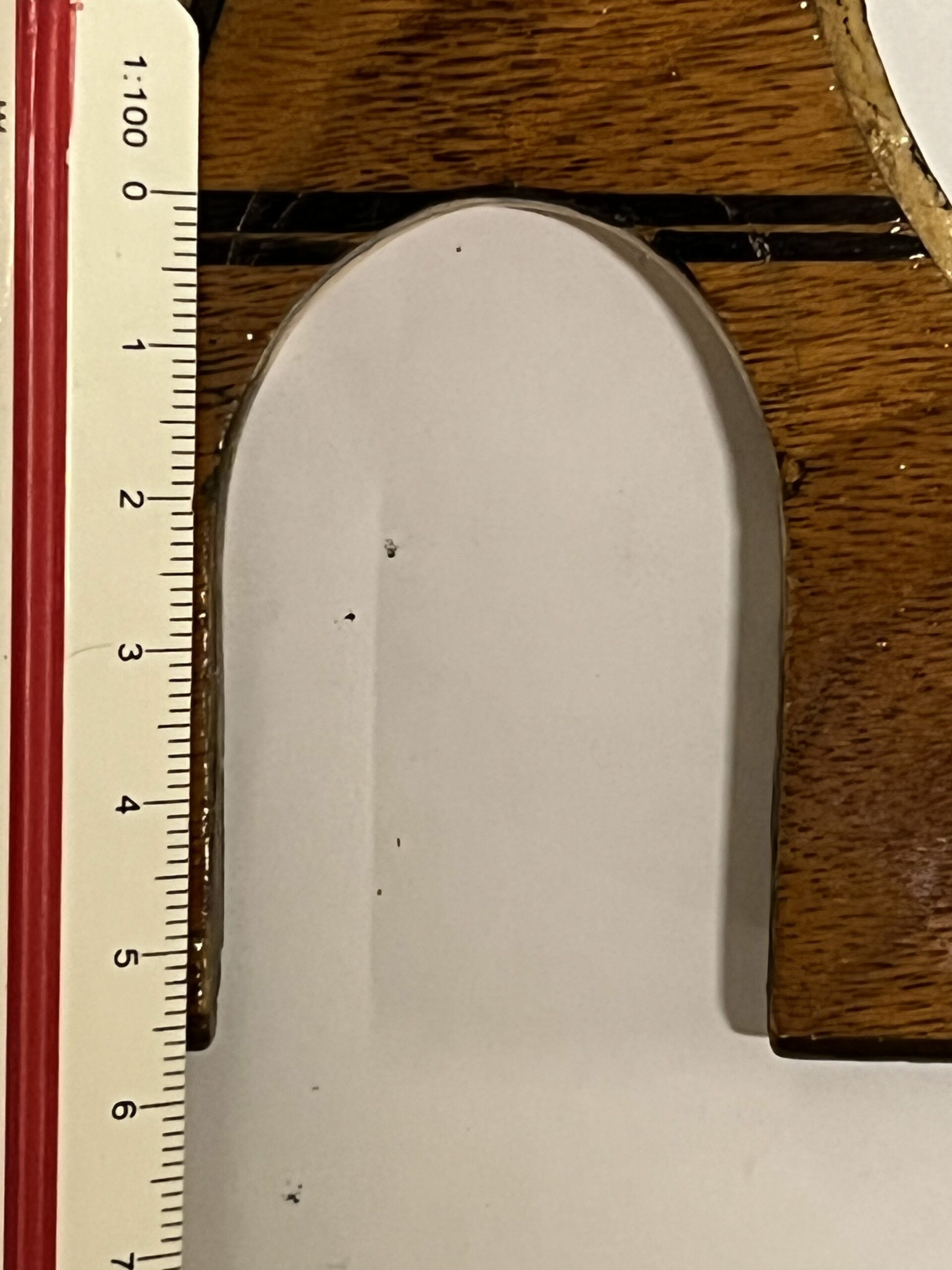
With a metal type tape measure attached (by magnet) to the bodyshell floor (seat and carpet removed to attempt to get an accurate measurement!) and pulled taught over the steering wheel we measure before and after.
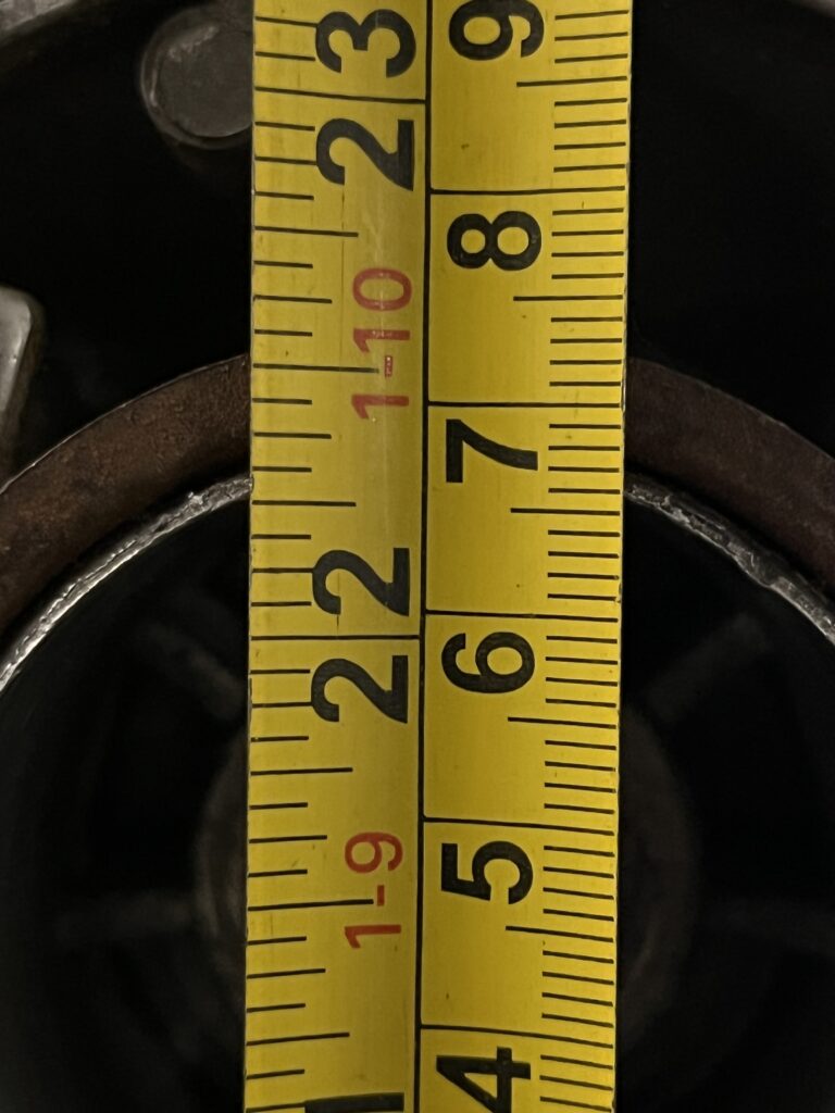
Measured at the steering wheel hub for the original bracket – a reference reading of approx. 572mm. (where the circular flange passes the tape)
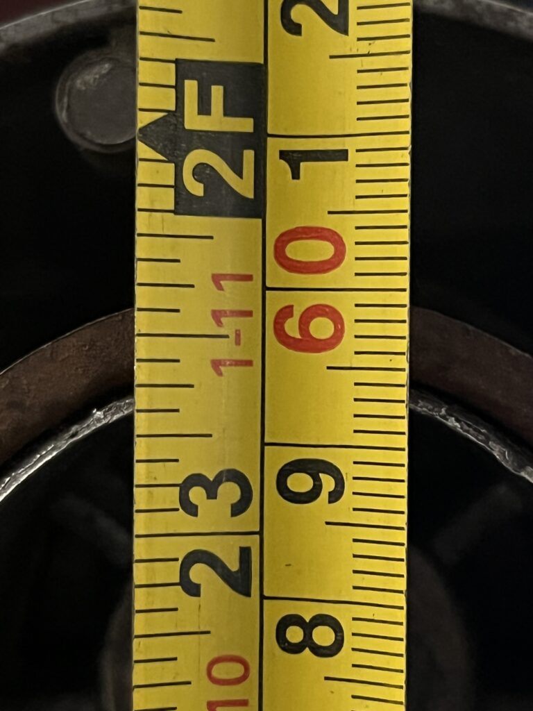
With the new bracket, the approx. 572mm becomes approx. 599mm – an increase of approx. 27mm.
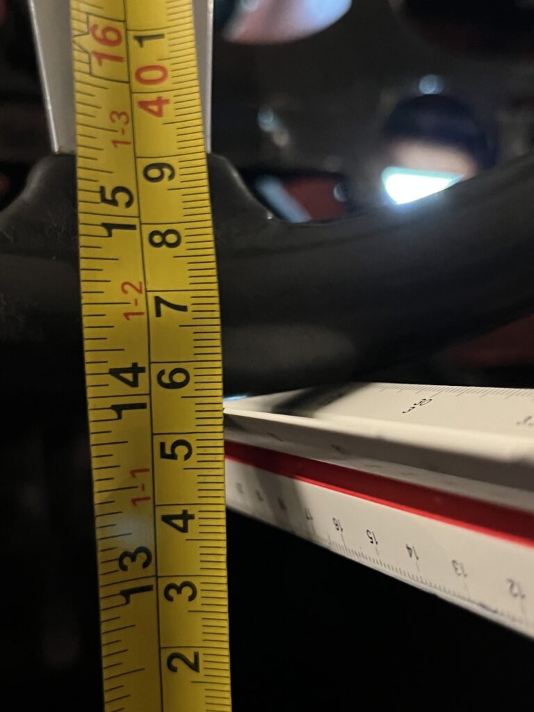
For the original bracket – measuring at the bottomost part of the steering wheel (holding a white scale ruler horizontal across the bottom of the steering wheel and measuring off the dimension on the yellow tape measure) we take a reference dimension of approx. 352mm.
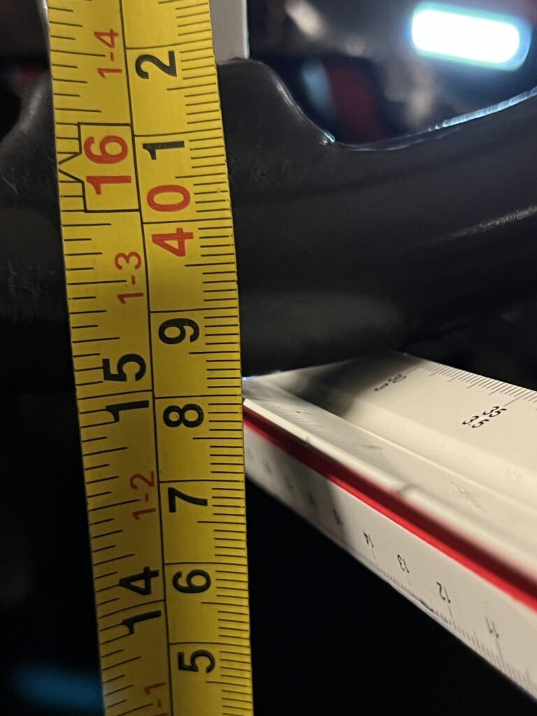
With the new bracket the approx. 352mm becomes approx. 379mm – an increase of approx. 27mm.
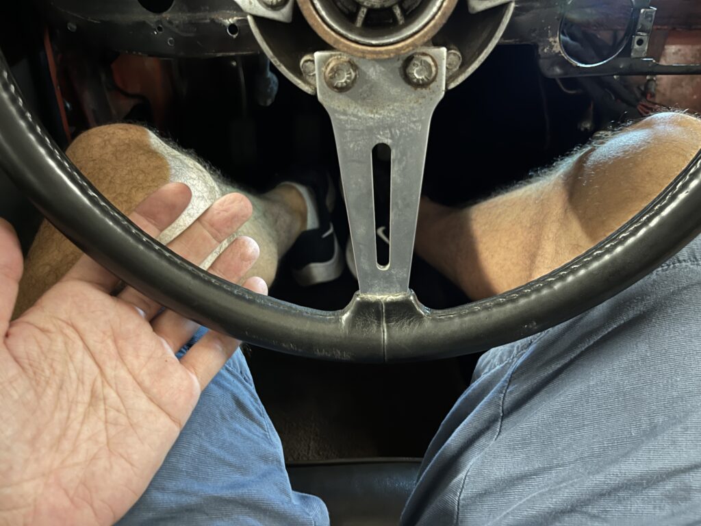
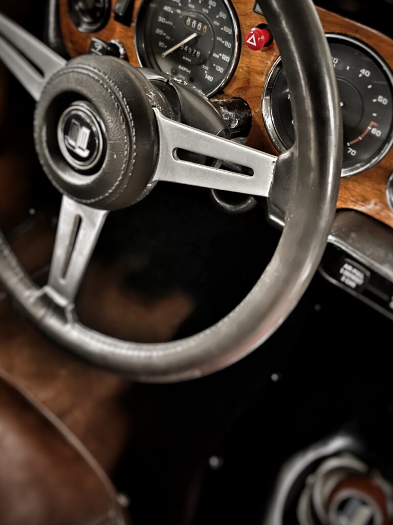
Last but not least, the most important part! Whilst difficult to photograph accurately, here I am sat behind the wheel (excuse the knees!), with the original bracket in place, my hand resting on my leg, I have just a little room between hand and steering wheel.
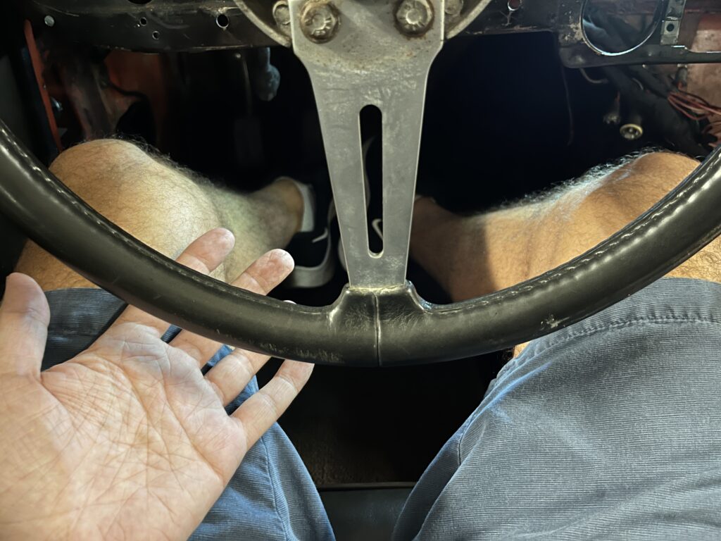
With the new bracket in place!
The effect is clear to see and immediately noticeable, even getting in and out of the car.
No longer need to put seat further back than ideal and an improved steering wheel driving position.
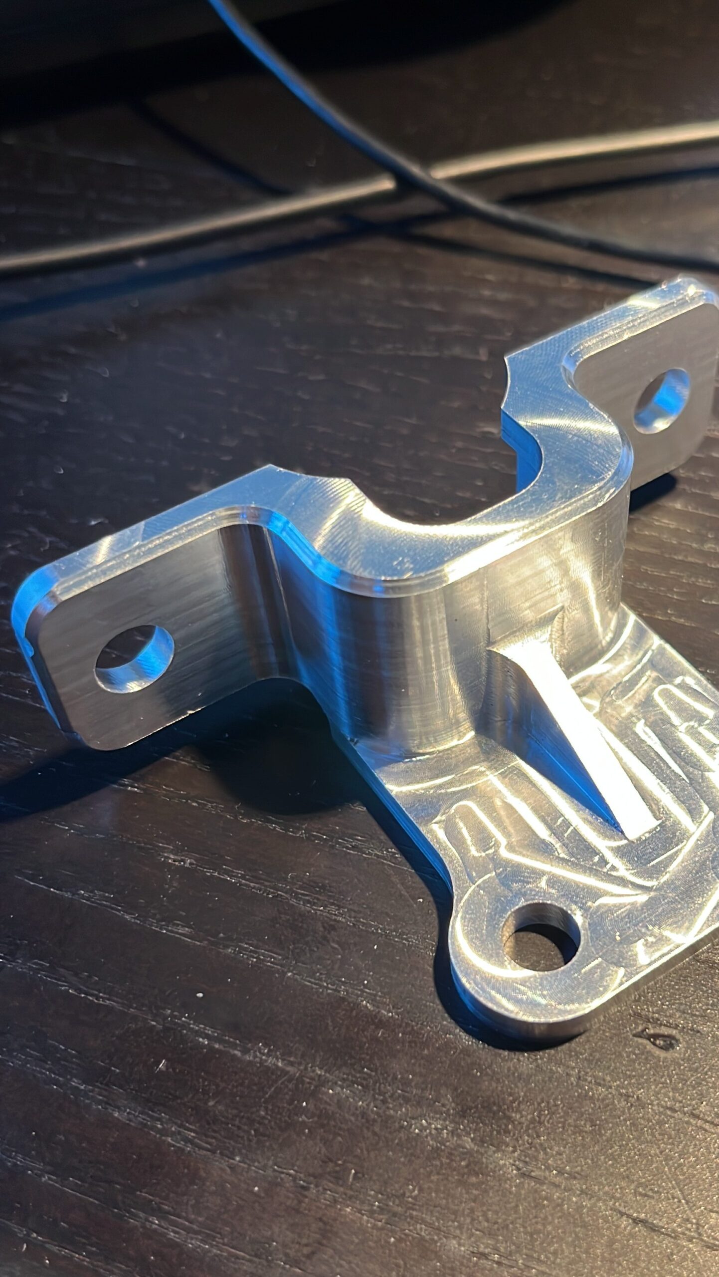
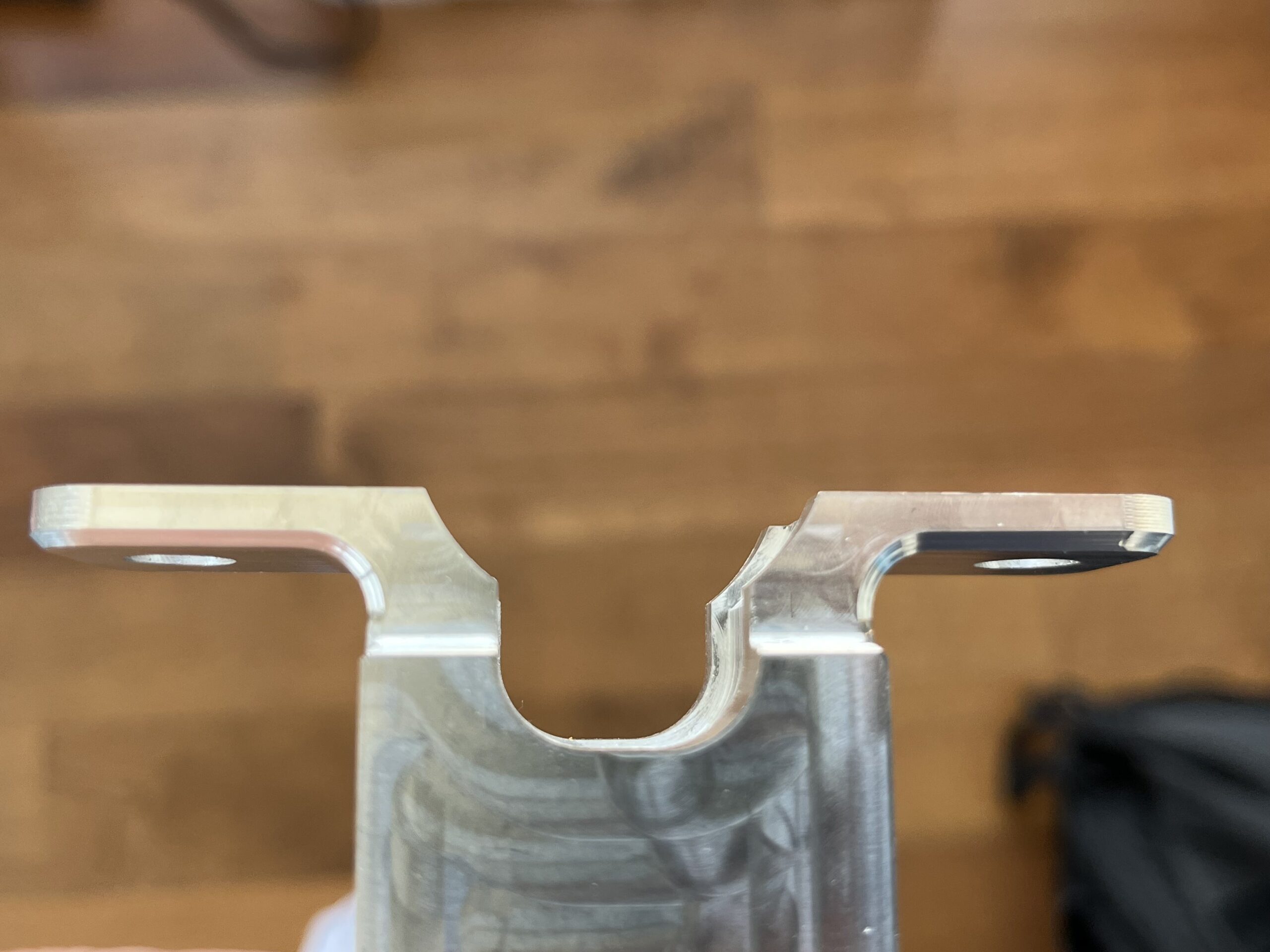
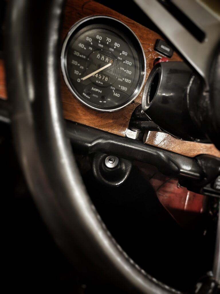
Closer photos with new bracket installed
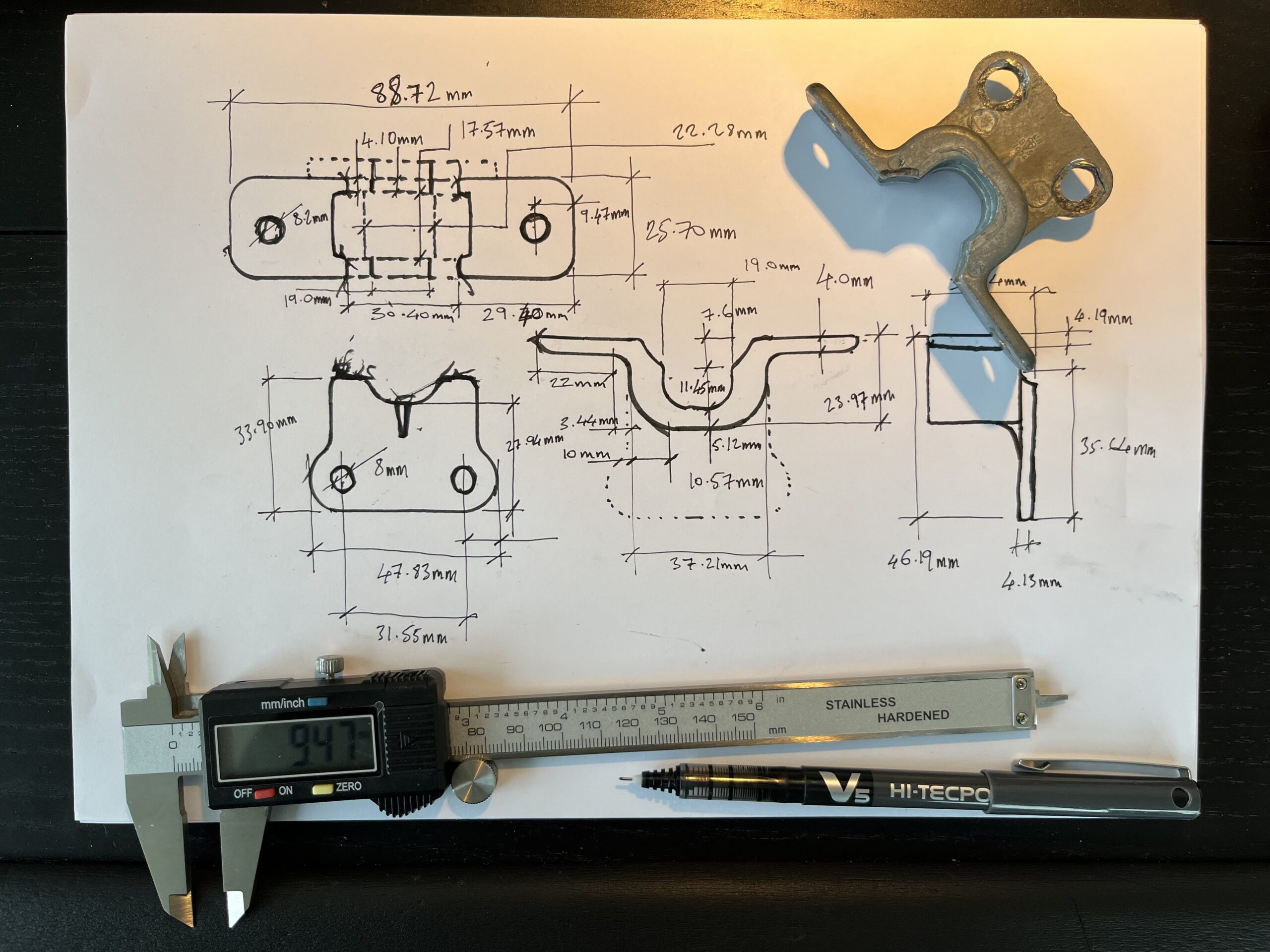
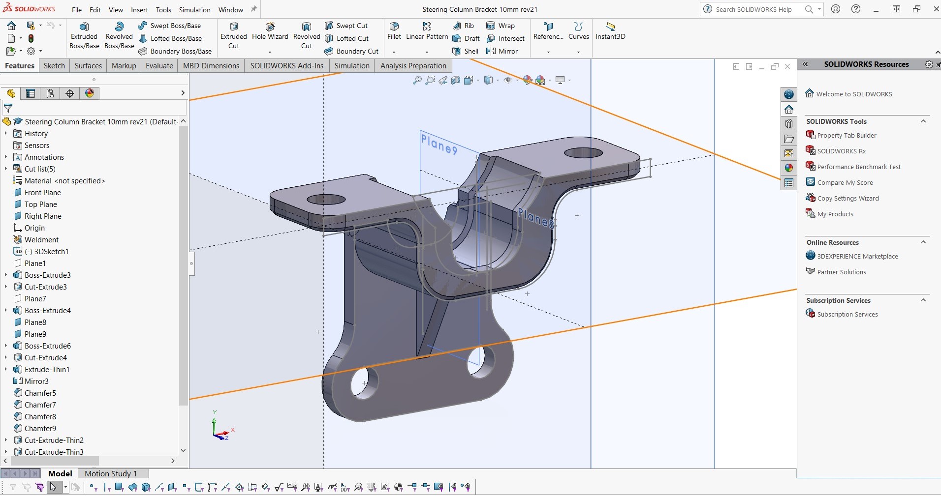
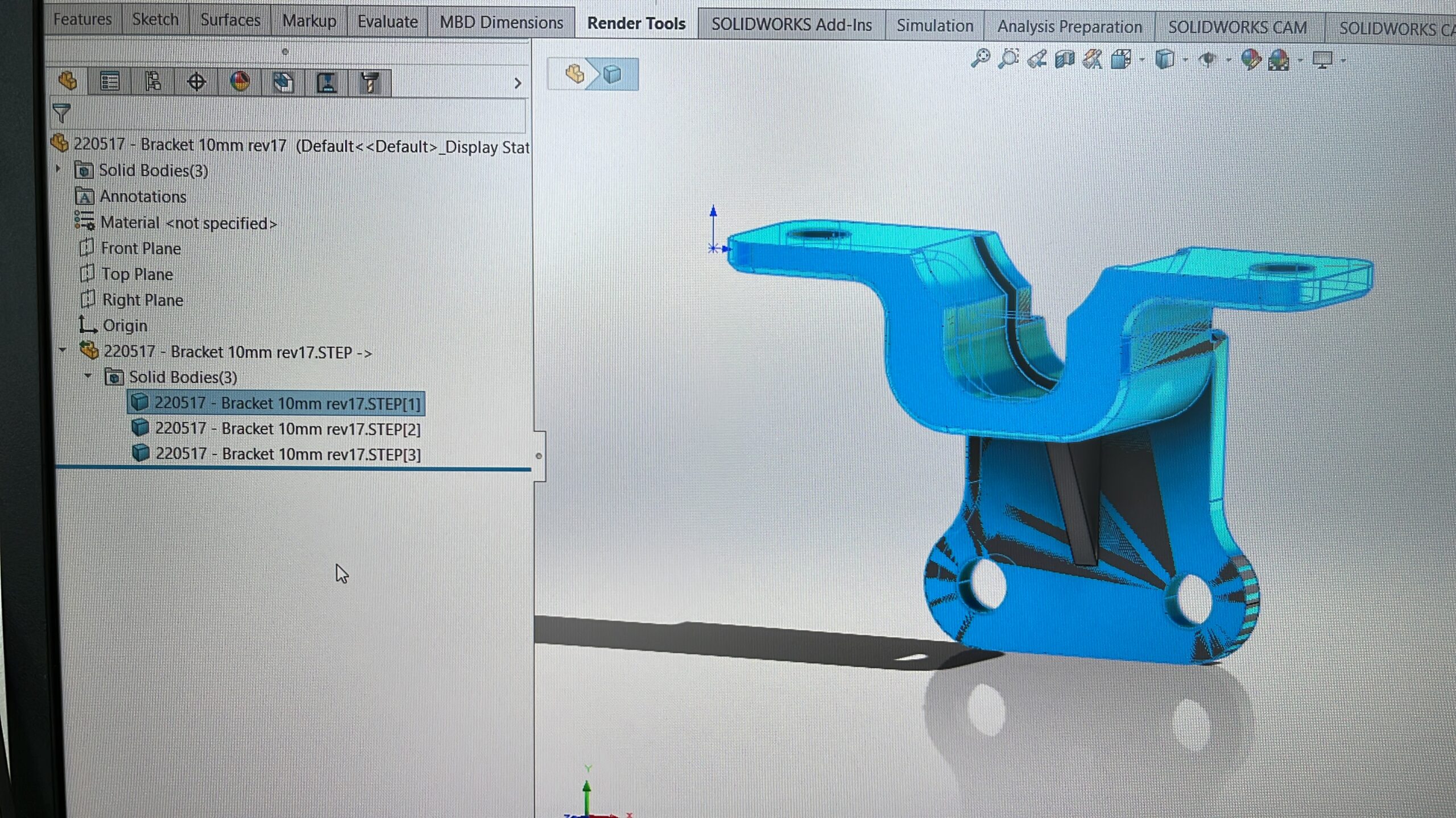
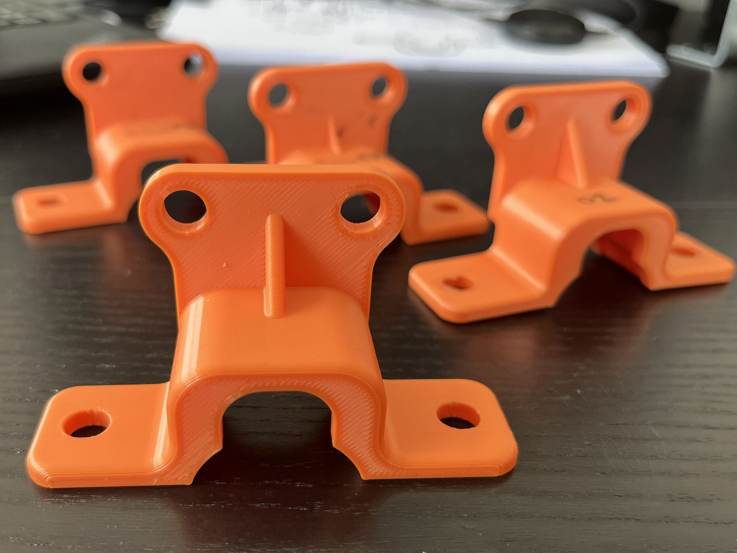
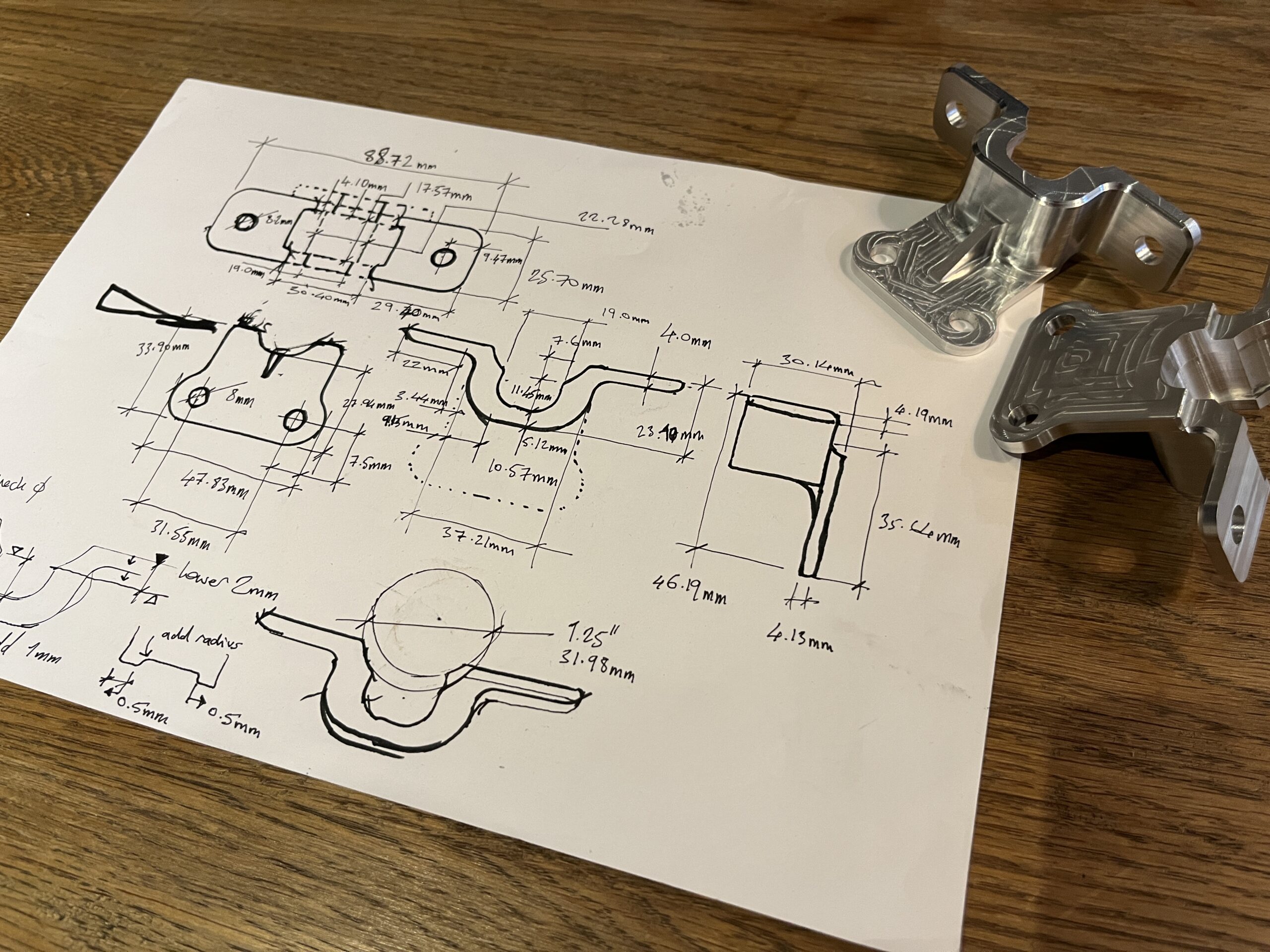
Development Images